People often think of wires as just metal paths that carry power and signals from one place to another. But in real systems, wires play an active role in what a device can do, how safely it works, and how long it lasts. As electronics became faster, more complex, and more safety-critical, wiring turned into a key design challenge.
Even in environments built for precision, wiring can become the weak link. NASA’s review of spacecraft wiring safety explains that to completely address the issue of wiring safety, it’s not enough to invent better insulation—the entire wiring system must also be considered.
That’s a blunt statement with broad implications: wires are part materials science, part electrical engineering, part systems reliability, and part human factors.
How wires “think”: when a wire becomes a transmission line
In low-speed electronics, a conductor often behaves like the simplistic diagrams in textbooks: a near-instant connection between nodes. At high speeds, a “wire” behaves less like a connection and more like a structure that launches and guides electromagnetic waves.
A high-speed PCB design guide puts it plainly: A PCB transmission line is a type of interconnection used for moving signals from their transmitters to their receivers on a printed circuit board, and it emphasizes that it’s composed of two conductors: a signal trace and a return path which is usually a ground plane.
That wording matters because it breaks the connector myth. If you only think about the signal trace and ignore the return path, you miss what the wire is at high frequencies—an EM system with geometry, dielectric material, and impedance.
The same guide explains why these design rules exist. It warns that non-uniform impedance causes signal reflections and distortion, and it adds that it’s crucial to not ignore the transmission line effects to avoid signal reflections, crosstalk, electromagnetic noise and other issues that can cause errors. In other words, wires don’t merely carry bits, they can reshape bits, echo bits, and corrupt bits.
This is why a modern device can fail in ways that look like “software bugs” but are actually wiring physics: a mistuned trace, a poorly controlled impedance, or a missing return path can turn a clean digital edge into a glitchy waveform.
The power side: wires set the voltage, heat, and whether the equipment behaves
On the power side, wire behavior is just as active. They have impedance, heat up when carrying current, and cause voltage to drop as electricity flows. While this might seem obvious, it’s actually a common cause of real-world problems, especially as devices use more power.
The IEC practice shares that the voltage drop is the reduction in voltage that occurs as current travels through a cable due to the conductor’s inherent impedance, and it stresses that the drop depends on factors such as the length of the cable and the cross-sectional area.
That is a direct reminder that wires don’t just deliver power—they transform it along the way, and that transformation can starve downstream components.
The same reference explains why wire choice becomes a product decision, not a mere installation detail: Excessive voltage drop can cause equipment malfunction and failures, and therefore standards dictate maximum permissible voltage drop limits.
When product teams plan performance targets, they’re implicitly betting on these electrical realities: deliver too little voltage at the load, and the behavior changes—motors stall, sensors misread, radios brown out, chargers throttle, and systems reset.
That also means wires become part of efficiency. If voltage drop forces higher currents for the same power, losses rise, heat rises, and battery life shrinks. The wire becomes a quiet tax on performance.
The frequency side: skin effect and the “invisible shrinking” of a conductor
As signals move faster and power electronics switch at higher frequencies, conductors exhibit a counterintuitive effect: current crowds toward the surface. This can make a thick conductor behave like a thinner one, effectively increasing resistance for AC and high-frequency components.
A historical review of skin effect summarizes the core concept directly. According to Maxwell, the current density in a conductor increases towards the conductor surface. This phenomenon is called the skin effect. The same paper adds that the skin effect affects in particular the inductance of a line formed by one or several long parallel conductors.
This is one of the most important reasons wires aren’t “just connectors.” At the frequencies used in modern switching regulators, high-speed buses, RF front ends, and even fast edges on digital signals, the physics of current distribution changes how much loss, distortion, and heating you get. The conductor’s geometry—round vs. flat, solid vs. stranded, spacing to neighbors—starts to decide system behavior.
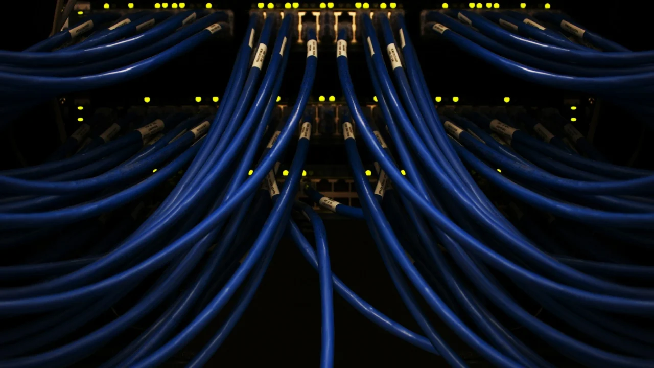
And the story doesn’t stop at a single wire. The same review describes a related phenomenon: The proximity effect refers to the dependence of the current density in a conductor on the proximity of other conductors through which a time-variable current is flowing. That’s a direct bridge to the real world: cable bundles, harnesses, and PCB traces don’t live alone. Wires influence each other. A couple of noises. They inject interference. They become an unplanned RF system.
Safety and failure: the wire is a system, not a part
Wiring isn’t only about speed and efficiency; it’s also about preventing catastrophic failure. In aerospace and other safety-critical systems, insulation behavior, routing, and environmental exposure can make wiring a hazard.
NASA’s wiring safety review highlights why this is treated as a system problem, not merely a material spec. It notes that “the arc-tracking problem with polyimide insulation” was identified as “an issue of concern,” and points out that different environments require different approaches.
This is one reason “wires are not just connectors” becomes a hard lesson in modern engineering. A connector-level mindset assumes faults are rare and localized. A systems mindset assumes faults can propagate, couple, and worsen—through bundles, insulation damage, contaminants, and environmental extremes. When you scale wiring across aircraft, spacecraft, or EV architectures, wiring reliability becomes a major contributor to overall system risk.
Why wires increasingly decide product design in 2026-era technology
Modern products push wires into roles that used to belong to chip-level logic. Data rates rise. Power densities rise. Safety requirements tighten. And systems become more distributed, which means more physical distance between computing, sensing, and actuation.
When high-speed design guidance says a controlled-impedance trace maintains the chosen impedance, Z0, from the source to the load, it’s describing an engineering promise: the wire must behave predictably across its length or the system will misbehave. That predictability now influences board layer stackups, grounding strategies, connector selection, and manufacturing tolerances.
When electrical sizing guidance says “voltage drop is influenced by the length of the cable” and “cross-sectional area,” it’s describing a direct trade-off between product form factor, cost, and reliability. Want a thinner cable for weight and flexibility? You may pay in voltage drop, heat, and reduced headroom. Want longer runs for modular designs? You may incur losses or have to redesign the power distribution.
Trade-offs: the hidden costs of treating wires as “simple”
When you see wires as active parts of a system, the trade-offs are easier to understand.
One trade-off is complexity. Designing signal trace and a return path correctly forces teams to care about stackups, reference planes, terminations, and routing rules. That adds design time, verification cost, and manufacturing constraints.
A second trade-off is bulk. Combatting voltage drop often means thicker conductors or higher voltages, and the reference warns that “the voltage drop dictates the active cable size for long route lengths.” Larger cables add weight and stiffness—painful in vehicles, wearables, robots, and aerospace hardware.
A third trade-off is safety margin. NASA’s framing—the entire wiring system must also be considered—is a reminder that safety isn’t guaranteed by any single insulation choice. Safer wiring can demand stricter installation procedures, better inspection, more robust routing, and more careful handling of environmental exposure—all of which carry cost.
How to think about wires like a modern engineer
The simplest way to update the mental model is to treat wiring as a set of behaviors rather than a passive part.
At high speeds, a wire is a transmission line with impedance, reflections, and crosstalk risk—so it must be designed, not merely connected.
At meaningful power levels, a wire is a voltage divider and a heater, and its inherent impedance can cause equipment malfunction and failures—so it must be sized and routed as part of product reliability.
At high frequencies and dense layouts, a wire is also a field problem, where current density increases towards the conductor surface and neighboring conductors can reshape current distribution through the proximity effect.
And in safety-critical environments, wiring is an integrated risk surface, where improving safety requires considering the entire wiring system, not only the material label on insulation.
Microchips may get the spotlight, but wires are where signals become real, where power becomes usable, and where failure can become physical. The next time a device feels mysteriously unstable, remember: the wire might be doing far more than connecting two points—it might be deciding what’s possible.